Technical Information
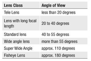
Angle of View
The angle of view is the area shown on screen. The angle is determined by the lens’s focal length and the corresponding sensor format.
see conversion table
Back Focal Length
Back focal length is the distance from the camera‘s lens flange to the sensor. In CCTV there are two different standards of lens mount commonly used, C-Mount which has a back focal length of 17.526 mm and CS-Mount which has 12.5 mm.
see C-/CS-Mount
Binning
In binning mode the charge of adjacent pixels is combined as one signal, horizontally, vertically or in both dimensions. Binning reduces the effective resolution of the camera, but achieves an increased sensitivity and signal-noise ratio by combining the pixel‘s information. Binning is often used for low light applications.
C-/CS-Mount
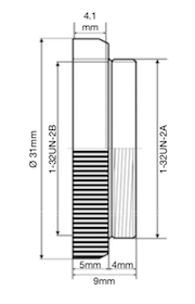 The C and CS mount connection is a one inch thread with a specification 1-32UN-2A or B or W 1 inch x 32 TPI (TPI = Thread per inch) and almost corresponds with the metric thread M 25.5 x 0.75 mm.
The angle of light projection for the one inch thread is 55°. However, the metric thread is 60°. By using a C/CS Mount adapter, C mount lenses can be used on CS mount cameras, but it’s not possible to use a CS mount lens on a C mount camera.
Camera Interfaces
Usually, industrial cameras transmit images to a PC. Necessary interfaces and protocols are Analog, FireWire, Camera Link™, Gigabit Ethernet™, USB 2.0/3.0.
Ricoh supports the interfaces Camera Link™ and GigE Vison™.
See also Camera Link™ and Gigabit Ethernet & GigE Vision™
Camera Link™
Camera Link™ is a high-end interface with very high data transfer rates. It is the standard of the Automated Imaging Association (AIA), in which renowned camera, frame grabber and software manufacturers of industrial image processing are united.
Advantages:
- Very high data transfer rates
Disadvantages:
- Additional components are necessary (e. g. frame grabber)
- System not interchangeable
Camera Modes
see Partial-Scan and Binning
CCD and CMOS Sensor
The basic function of CCD and CMOS image sensors in the camera is the conversion of light (photons) to electrical signals (electrons).
CCD Sensor
CCD sensors are light-sensitive electronic modules that are based on the internal photoelectric effect. All CCDs consist of an array (field) of light-sensitive photodiodes. CCD is the abbreviation of Charge Coupled Device, which is used in the CCD sensor. In a CCD, the charges are gradually shifted into registers and then read out.
In addition to CCDs, CMOS sensors are increasingly being used, as the CCD‘s disadvantages (noise, lower sensitivity) are minimized.
CMOS Sensor
In a CMOS sensor, the conversion of light to electrons is done by electronic components which are located directly on the pixels. Thus, they can be read directly instead of out of the register as with the CCD sensor.
Characteristics of CMOS sensors such as light sensitivity, number of pixels, readout speed, chip size, noise or the noise related to the dynamic range have been improved significantly and are equal or better than those of CCD sensors. CMOS sensors are more compact, cheaper and with much lower power consumption.
Coatings (anti-reflection coatings)
High-quality coatings reduce the scattering of light inside the optics of a lens. Reflections inside the optic cause a series of undesired effects:
- For pictures with a high intensity of illumination (e.g. due to the light source itself or sun light), nebular, spot-like reflections and ghost images are being generated.
With nebular reflections, low-contrast images can no longer be displayed due to the loss of contrast. - With CCD sensors, single bright reflexes lead to phantom images which can pass over the whole picture. Punctual overloading will lead to the typical "smear" effect on the CCD sensor.
Another very important detail is the abrasion resistance of the coating. After each cleaning of the lens surface, the coating should neither be rubbed off or it’s thickness be changed. Only extensive pre-treatment of the glass surfaces guarantees a long life-time of the razor-thin coating.
Colour correction
Lenses where red and blue spectral components have been corrected are called achromatic lenses. When they are additionally corrected for green light, they are called apochromatic lenses. And when they are corrected for RGB and near infrared, they are called superachromatic lenses.
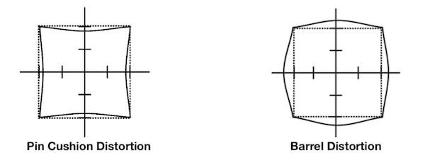
Distortion
It is one of the properties of lenses to produce more distortion towards the image border. Straight lines close to the image border are bent outwards or inwards (distorted). Barrel distortion is when the lines are bowed outwards and pin cushion distortion when the lines are bowed inwards (see figures below). In general, a lens with lower distortion is of a higher quality than a lens with higher distortion.
Entocentric Lenses
 Most of the lenses in the machine vision field are entocentric lenses. Here, lenses with fixed focal length (fixed angle of view) and zoom lenses (variable angle of view) are based on the same optical principle and match the perspective of a human eye.
An angle of view of about 50° corresponds to the human eye, therefore, lenses with such an angle of view are called standard lenses. Based on the angle of view, lenses can be divided into different classes.
Entocentric lenses are used in many applications – including quantity checks, pick & place applications, print inspection, colour and barcode reading.
Filter
UV cut filter
UV cut filters block UV-light from entering the lens, but allow visible and IR light to pass through. Often UV filters are used to protect the valuable front glass element of lenses.
Polarising filter
Polarising filters are used to eliminate reflections coming from windows, water etc. The filter is attached to the front end of a lens and rotated until it blocks the unwanted reflection.
Colour Filter
Colour filters let only a certain colour (= rays with a certain wavelength) pass through to the imaging sensor. For example, only red light passes a red filter. Colour filters are used to emphasize certain details of an image or to reduce disturbances.
- Additional components are necessary (e. g. frame grabber)
- System not interchangeable
Floating Focus Mechanism
Floating focus mechanism
Focal Length (f)
The focal length of an optical system is the distance between the focal point and the related principal plane (or prin- ciple point). An imaging system has two principle planes and thereby two focal lengths. Both focal lengths are equal, when a medium with the same refractive index is located on both sides of the imaging system. In a thin lens, both prin- ciple planes coincide in the center of the lens. In this case, the focal length is equal to the distance of the focal points to the center of the lens.
Focus
Setting up the focusing of a lens is always more accurate when it is done with the iris open and the depth of field at its minimum.
Focus Shift
Light with shorter wavelengths are generally more refracted than light with longer wavelengths. That means, visible light (about 380 nm to 780 nm wavelength) is more refracted than IR light (780 nm to 1400 nm).
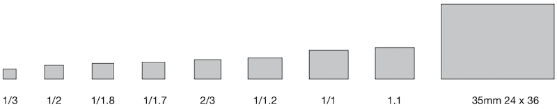
Format 1/3", 1/2", 2/3", 1", 4/3"
Format determines the image circle of a lens that covers the size of the corresponding sensor in a camera. The sizes are given in inches, as image sensors replaced video tubes from the past whose dimensions were specified in inches.
Lenses with a larger format can be used on cameras with smaller image sensors without restriction but not vice versa, as otherwise shading appears in the corners. However, when using a 2/3" lens on a 1/3" camera the specified angle of view for the lens changes.
see conversion table
Whilst in the past sensor sizes in cameras have become increasingly smaller, the current trend is towards large sizes of 1" and 4/3", because the pixels are larger.
Frame Rate
The frame frequency or frame rate (fps = frames per second, f/sec) indicates the maximum number of unique conse- cutive images a camera can produce. The frame rate is, inter alia, depending on the exposure time. Very high frame rates can be achieved with CMOS sensors, since their pixels are not read out by registers but by electronic compo- nents which are located directly on the pixels, unlike to CCD sensors.
Gigabit Ethernet & GigE Vision™
GigE Vision™ is a new standard in the industrial image processing market. It defines the hardware standard of the widespread Gigabit Ethernet interface, as well as the software standard for the communication protocol. The so-called GenCam interface (generic programming interface for all kinds of cameras) allows a cross-vendor standard and access to the functionalities of the devices and is part of the GigE Vision™ standard. Proprietary solutions are avoided.
Benefits of GigE Vision™:
- High data transfer rates of 100 MB/s
- Usability of existing Ethernet infrastructures
- Cable length up to 100 m
- High degree of standardisation by Gigabit Ethernet and GigE Vision™ standards
- Use of hardware technologies from the mass production (controller chips, network devices, switches, cables, connectors, ...)
High Resolution
Lenses are determined to be of high resolution if they can display a larger number of line pairs per millimeter at higher contrast than standard lenses (measured against the current standard / Æ see also resolution MTF). High-resolution lenses reproduce images more accurately than standard lenses. In particular, even with low level illumination high-contrast images are still generated.
Image Format
For monitors and cameras, there is a distinction between different image formats. The well-known VGA format has a size of 640 x 480 pixels. Thereby, the aspect ratio between horizontal and vertical axis is 4:3. Other formats are 4:3 XGA (1024 x 768) and UXGA (1600 x 1200). The most common 16:9 formats are HD 720 (1280 x 720) and HD 1080 (1920 x 1080).
Image Frequence
see Frame Rate
Image Sensor
see CCD Sensor and CMOS Sensor
Iris (F)
The iris reduces the amount of light, which passes through the lens, by reducing the aperture. The mechanical control of the aperture is achieved by a circular arrangement of a number of overlapping slats, which change the aperture‘s size.
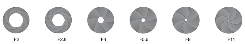
In contrast, the shutter of a MV camera changes the sensor readout time electronically and thus controls the time of exposure (see shutter). By separate settings of illumination, iris and sensor readout time, it is possible, to use the effect of different apertures. By cutting off the peripheral rays when closing the iris (= larger F-No.) certain lens errors are reduced and the depth of field increases.
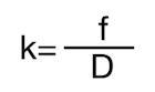 The size of the aperture (k) is calculated by taking the focal length ratio (f) and divide it by the diameter of the iris opening (D).
Aperture values are international standards. The aperture levels change at a factor of 2 . On the below chart, from one aperture rating to the next, the amount of light doubles or halves, depending on which direction you are going. So, from an aperture of F8 to F16 the quantity of light will reduce to one quarter.
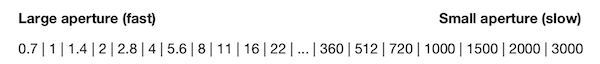
A common iris range is F1.4 - F360, which means that with the iris fully open it is operating at F1.4 and with it closed down as far as possible (and the use of the built in neutral density filter) the aperture is F360.
JIIA S-Rank Performance
The JIIA (Japan Industrial Imaging Association) produced a technical report (JIIA LER-007-2012Rev2) recommending the optical specification of lenses for high resolution cameras (sensors with a pixel size of less than 7.6µm).
These high-resolution lenses are divided into S-Rank and A-Rank by optical performance, primarily by resolution and the classifications are as follows:
(1) S-Rank:
High Performance Lenses where the specifications are available over the entire image area. The lens should completely resolve* at the Nyquist frequency over the full image area.
(2) A-Rank:
Standard Performance Lenses where the specifications are available over a large amount of the image area. The lens should resolve* at the Nyquist frequency in the center of the image area and should resolve 70% of the Nyquist frequency at the maximum height of the image area.
* The resolution should be better than 20% of the contrast ratio in MTF.
Nyquist frequency as the evaluated spatial frequency should be calculated using the following equation:
fNq = 1/(2 x p )
fNq : Nyquist Frequency (lp/mm)
p : Pixel Size (mm)
Frequency by number of Pixels (Typical)
|
Sensor Size Diagonal |
Image Height |
1 Megapixel |
2 Megapixels |
5 Megapixels |
10 Megapixels |
||||
|
S-Rank |
A-Rank |
S-Rank |
A-Rank |
S-Rank |
A-Rank |
S-Rank |
A-Rank |
||
|
2/3” 11mm |
Center |
66 |
66 |
93 |
93 |
147 |
147 |
207 |
207 |
|
Periphery |
46 |
65 |
103 |
145 |
|||||
|
1/2” 8mm |
Center |
90 |
90 |
128 |
128 |
202 |
202 |
285 |
285 |
|
Periphery |
63 |
90 |
141 |
200 |
|||||
2MP S-Rank Performance
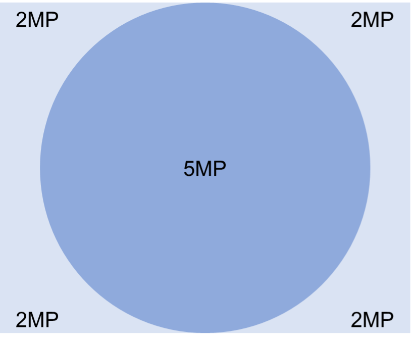
Our Exceeding 2/3" 2MP lenses can be used with 2/3" 5MP (Sony IMX250) Sensor with A-Rank Performance
Exceeding 5MP S-Rank Performance
As entire field 5 Megapixel camera lenses with 8, 12, 16, 25 and 35mm focal lengths, these lenses have virtually no image quality deterioration at the edges, and even at distances outside their optimum design criteria, they clear Ricoh’s strict standards ensuring fine optical characteristics. We can confidently recommend these lenses for use as high-resolution machine vision lenses as they capture 147 lp/mm high resolution, low distortion images not just from the center to the periphery but over the entire image measurement field
Our Exceeding 5MP lenses can be used with 2/3" 8.9 MP (Sony IMX267) Sensor with A-Rank Performance
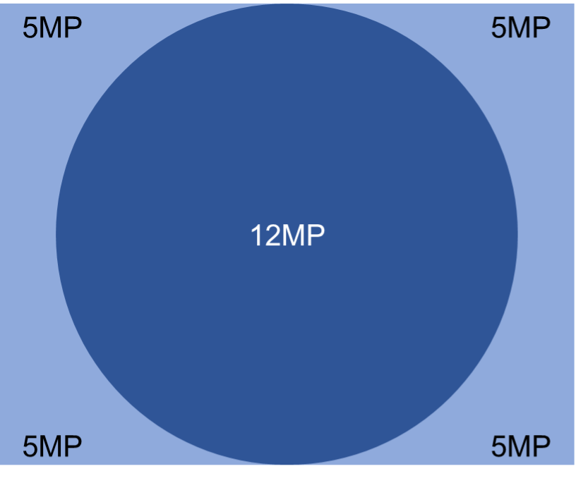
9MP (1”) / 12MP (1.1”) S-Rank Performance
Our 9 Megapixel (1”) / 12 Megapixel (1.1”) lenses are available in 12, 16, 25, 35, 50 and 75mm focal lengths. They also have virtually no image quality deterioration at the edges, and even at distances outside their optimum design criteria, they clear Ricoh’s strict standards ensuring fine optical characteristics. We can confidently recommend these lenses for use as high-resolution machine vision lenses as they capture 147 lp/mm high resolution, low distortion images not just from the center to the periphery but over the entire image measurement field.
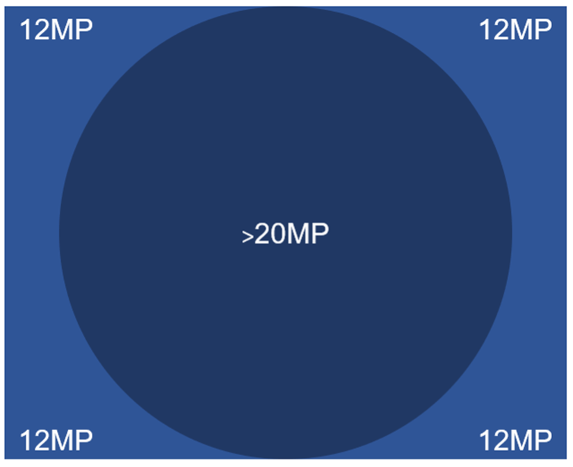
Our 9MP (1”) / 12MP (1.1”) lenses can be used with 1” 20MP (Sony 1MX183) Sensor with A-Rank Performance.
Line-Scan Lens
Low Distortion
Optically designed to reduce distortion, which poses a problem in image measuring and recognition, these lenses keep TV distortion to less than 0.1%1 (Figure 1), making them ideal for capturing low distortion images over the entire image measurement field.
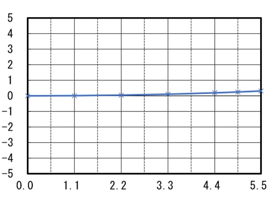
Figure 1. (Distortion)
By achieving low distortion, image deterioration in the surrounding area is suppressed. Conversely, with a standard 5 Megapixel lens at a working distance (W.D.) of 100mm and set at F:1.8 as in the below example, you can see that peripheral distortion is noticeable.
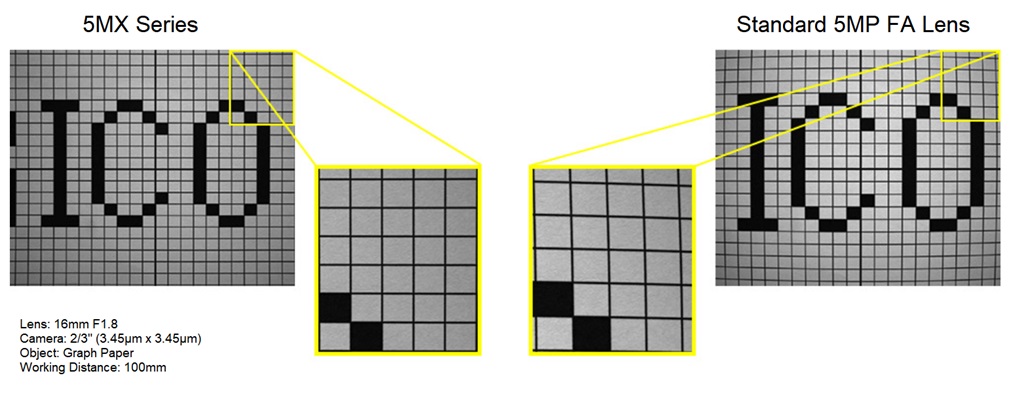
Figure 2.
1 Except 8mm
Macro Focus Mount (FP-MUVG, FP-MU2M)
The Macro Focus Mount is a special camera mount with a 2 mm tube extension. The C-Mount back focal length will be extended by 2 mm to 19.526 mm which will in turn reduce the lenses minimum object distance (MOD). In order to use our Macro Focus Mount, remove the standard C-mount on the lens and replace with the appropriate mount above. Please ensure you use the correct mount for the lens. In order to achieve even higher magnifications you can also use the close up adaptors and extension tubes.
MOD (Minimum Object Distance)
The minimum object distance refers to the minimum distance from the front of the lens that an item will remain in focus. To reduce a lens’s MOD you can install extension tubes and spacers between the lens and the camera which moves the lens further away from the CCD. The further the lens is from the CCD the closer the MOD. Please note reducing the MOD of a lens in this way affects focus at longer distances.
MTF (Modulation Transfer Function)
See Resolution
OTF (Optical Transfer Function)
See Resolution
Partial Scan
Partial scan allows only a portion of the image sensor to be read. This can either be a freely chosen image detail or an image strip that is a half, quarter or eighth of the image.
Since the size of a partial image is smaller, the camera can capture more images per second, without exceeding the maximum data transfer rate of the camera.
Partial scan is more difficult with CCD sensors, since each entire sensor row is read and thus omission of pixels on the left and right side in a row provide no speed advantage.
CMOS cameras are not affected by these restrictions, since each pixel is surrounded by its own signal transducer and thus a fast readout is possible. Pixel size and pixel pitch
The pixel pitch is the direct distance between the pixels of an image sensor or monitor, measured from pixel center to pixel center. Pixel pitch is not the same as the pixel size.
The pixel size can be different for the same size sensors with identical number of pixels as the pixel pitch varies.
Protrusion
Some C-mount lenses protrude deep into the camera flange. Therefore, it is possible that a lens touches with the front surface of the glass filter in the camera, or even cannot be screwed in. 3-CCD cameras often require lenses with a maximum rear protrusion of 4.0 mm. The prism block in front of the CCD prevents the use of lenses with larger protrusions.
Resolution (modulation transfer function)
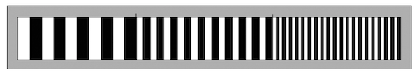
Resolution refers to the distinctness of fine structures. Using a test chart with line pairs per millimeter which get increasingly closer together, the contrast of a lens can be measured.
In the image of the test chart structures with increasing fineness and located closer to the edges of the image become "blurred". The highest optical performance of a lens is usually in the center of the image. The finest structures, which are just discernible, indicate the resolution limit of each lens.
Indicating the brightness of white with 100% and of pitch-black with 0%, the contrast and difference in brightness with increasing line pair density becomes smaller.
The optical performance of an optical system is shown in a diagram, the MTF curve (modulation transfer function). In that diagram, structure fineness (lp / mm = line pairs per mm) can be read in relation to the given contrast from the optical center to the edges.
Reversing ring (for microscopy)
A reverse ring screws to the front filter of a corresponding lens and allows it to attach to the camera in reverse. This creates an extremely short MOD and allows the lens to focus only millimetres from an object. An additional extension tube allows an even closer approximation to the object. The realisable magnifications are of high quality and brightness.
Discover our products following the link /Reversing-Rings.html
Additionally see the Using of a Reversing Ring
Shutter
In photography the "Shutter" is, figuratively speaking, a flap, which regulates the exposure time of an image. For video cameras, a mechanical shutter is not appropriate, because it is too slow and would have a high grade of wear. Thus, video cameras have an electronic shutter.
A distinction is made between global shutter and rolling shutter.
CCD sensors always have a global shutter, in which the entire sensor is exposed. Most CMOS sensors have a rolling
shutter, which exposes the sensor line by line. Recently, there are also CMOS sensors with a global shutter.
Global Shutter
With a global shutter, deletion and subsequent exposure of all sensor lines is simultaneous. At the end of the exposure all data from each row is moved simultaneously to the end. From here the reading of each line is then performed separately.
The simultaneous exposure of all lines has the advantage that the image of a moving object is reproduced wit- hout distortion. Sensors working with the global shutter method, however, are more complex than sensors with a rolling shutter.
Rolling Shutter
With a rolling shutter, deletion and subsequent exposure of the sensor takes place line by line slightly delayed. At the end of the exposure, the lines are read successively. As a result, a time lag occurs between the exposure of the first and the last sensor line, the image of a moving object is distorted.
Telecentric Lenses
Telecentric lenses are usually used for measurement tasks, because they can measure objects in changing positions without distorting the perspective.
With telecentric lenses, the angle of view is virtually zero degrees within a certain zone (telecentric zone). Hence, the light path is almost parallel and the image is without perspective error. Each object will appear at the same size regard- less of their distance. In spatial structures, such as holes, the sides are not seen because the lens looks straight down the hole!
The diameter of the front lens of a telecentric lenses must be at least as large as the object.
Transmission
Transmission indicates the amount of light, which reaches the sensor after passing through a lens. Typically, the transmission is specified for a wavelength range from 300 nm to 1200 nm (light is visible for the human eye between about 380 nm and 780 nm). The transmission range is from 0% (no light transmission) up to almost 100% (maximum light transmission).
Trigger Functions (Trigger modes)
Machine vision applications usually work with triggered image recording. Since industrial cameras have no mechanical shutter for exposure control, the sensor is exposed continuously. In order to limit this ongoing exposure a trigger function is used.
- With a hardware trigger, triggering is caused by an external impulse, such as a light barrier.
- With a software trigger, the trigger signal is software controlled.
Standard trigger modes in camera technology are pulse width trigger (pulse width control) and the edge preset trigger (edge default). For both trigger modes the camera starts the exposure at the rising edge of the trigger signal, and terminates at the falling edge. The term "edge" denotes the change of a digital signal, i.e. the transition from low to high (rising edge) or high to low (falling edge).
The exposure time with an edge width trigger is additionally controlled by a value set in the camera.
Types of Lenses
See Entocentric Lenses and Telecentric Lenses
UV Lenses
Vignetting (decrease of ambient light)
Vignetting is a reduction of brightness and/or saturation at the edges of an image compared to the center. It is caused by mechanical (artificial) or physical (natural) effects. By closing the iris, vignetting can be reduced.
Conversion Table for Horizontal Angle of View
Lenses can be used on cameras with a smaller sensor, but not vice versa. By doing this, the viewing angle will change according to the table below.
| Format | 1/3 | 1/2 | 1/1.8 | 1/1.7 | 2/3 | 1/1.2 | 1/1 | 1.1 | 35mm 24x36 1) |
|---|---|---|---|---|---|---|---|---|---|
| Sensor (mm) | |||||||||
| Horizontal | 4.8 | 6.4 | 7.2 | 7.5 | 8.8 | 11.3 | 12.8 | 14.2 | 36.0 |
| Vertical | 3.6 | 4.8 | 5.4 | 5.6 | 6.6 | 7.1 | 9.6 | 10.4 | 24.0 |
| Diagonal | 6.0 | 8.0 | 9.0 | 9.3 | 11.0 | 13.4 | 16.0 | 17.6 | 43.3 |
| Focal Length (mm) | |||||||||
| 4.2 | 56.4 ° | 74.6 ° | |||||||
| 4.8 | 50.2 ° | 67.4 ° | 73.7 ° | 76.7 ° | 85.0 ° | 150.0 ° | |||
| 6.0 | 41.1 ° | 56.1 ° | 61.9 ° | 64.7 ° | 72.5 ° | 143.0 ° | |||
| 8.0 | 31.4 ° | 43.6 ° | 48.5 ° | 50.8 ° | 57.6 ° | 132.1 ° | |||
| 8.5 | 29.7 ° | 41.3 ° | 45.9 ° | 48.2 ° | 54.7 ° | 129.4 ° | |||
| 12.0 | 21.2 ° | 29.9 ° | 33.4 ° | 35.1 ° | 40.3 ° | 50.4 ° | 56.1 ° | 61.2 ° | 112.6 ° |
| 12.5 | 20.4 ° | 28.7 ° | 32.1 ° | 33.8 ° | 38.8 ° | 48.6 ° | 54.2 ° | 110.4 ° | |
| 16.0 | 16.0 ° | 22.6 ° | 25.4 ° | 26.7 ° | 30.8 ° | 38.9 ° | 43.6 ° | 47.9 ° | 96.7 ° |
| 25.0 | 10.3 ° | 14.6 ° | 16.4 ° | 17.3 ° | 20.0 ° | 25.5 ° | 28.7 ° | 31.7 ° | 71.5 ° |
| 35.0 | 7.4 ° | 10.4 ° | 11.7 ° | 12.4 ° | 14.3 ° | 18.3 ° | 20.7 ° | 22.9 ° | 54.4 ° |
| 48.0 | 5.4 ° | 7.6 ° | 41.1 ° | ||||||
| 50.0 | 5.2 ° | 7.3 ° | 8.2 ° | 8.7 ° | 10.1 ° | 12.9 ° | 14.6 ° | 16.2 ° | 39.6 |
| 75.0 | 3.5 ° | 4.9 ° | 5.5 ° | 5.8 ° | 6.7 ° | 8.6 ° | 9.8 ° | 10.8 ° | 27.0 ° |
| 78.0 | 3.4 ° | 4.7 ° | 5.3 ° | 5.6 ° | 6.5 ° | 8.3 ° | 9.4 ° | 26.0 ° | |
Angles of view in this table are calculated. Individual lens angles of view may vary according to optical design.
1) Indication only